5 Inch 800x480 Capacitive Touch DSI HDMI Display IPS TFT Screen
Raspberry Pi and Windows Compatible
5 Inch 800x480 Capacitive Touch Screen Display IPS TFT Raspberry Pi
Compatible
Overview
- 800x480 resolution display, IPS full view
- Raspberry Pi MIPI DSI interface direct output, plug and play, no
need to install driver
- Support official system Raspbian, 2 points for zoom the page
- Support Ubuntu/Kali/Win10 IoT, single touch
- Support Retropie
- Backlight adjustment through KEY, IIC command and PWM, adapt to
different use environment
Technical Specifications
| LCD Size | 5 inch | LCD Type | IPS TFT |
| LCD Resolution | 800*480 | LCD Interface type | RGB888, 16.7 M true color |
| Module Interface Type | Raspberry Pi MIPI DSI | Refresh Rate | 60Hz |
| Touch screen type | Capacitive touch screen | Viewing Angle | IPS:178° |
| Active Area | 108.00x64.80(mm) | Working Voltage | 3.3V |
| Maximum Operating Current | 340mA | Operating Temperature | -20℃-70℃ |
| Module Size | 121.1x77.9(mm) | Package Size | 154*143*38(mm) |
| Module Weight (net weight) | 112 g | Package Weight | 180g |
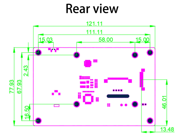
Product Dimensions
Package Contents
Hardware Features
Side Keypad
For brightness adjustment, click to increase by 10%, then return to
10% after reaching 100%; Long press to turn off the backlight and
press again to restore the original brightness.
MIPI DSI Interface
MIPI DSI interface for connecting Raspberry Pi via FPC flexible
cable, Specification for 15PIN 1.0mm
Backlight Control Mode Selection
The circuit is used to choose the mode of fixed maximum brightness
value or the mode of adjusting brightness value through PWM:
- The 0R resistor is soldered to lower pad, then the backlight value
is fixed to control by KEY
- The 0R resistor is soldered to upper pad, then the backlight value
is fixed to control by PWM
Note: The default option is set to control backlight value by KEY
External PWM Access Point
Used for external PWM control signal input, you can control the
backlight value through the PWM signal. Where the PWM point is
connected to the GPIO (such as GPIO18) that outputs the PWM signal,
and the GND point is connected to the GND pin.
Fan Power Interface
3.3V small fan can be connected.
Installation Guide
The module can be driven directly using the official original image
without any modifications.
Steps to use the module on Raspberry Pi:
- Download the latest system image from the official website of
Raspberry Pi to the PC, and then extract the file to get .img file
(https://www.raspberrypi.org/downloads/)
- Prepare a Micro SD card (at least 8GB), insert it into PC with the
card reader, open SDFormatter software, select the target SD card,
and then click the Format button to Format the SD card
- After the formatting is completed, open Win32DiskImager software,
first select Device (Micro SD card inserted on PC), then select
Image File (decompressed.IMG Image File), and finally click Write
for burning
- Pop out the SD card on the PC and insert it into the SD card slot
of Raspberry Pi
- Install Raspberry Pi into the display module:
- Install 4 copper columns to the positioning column
- Use 4 screws (M2.5) to fix the Raspberry Pi to the copper column
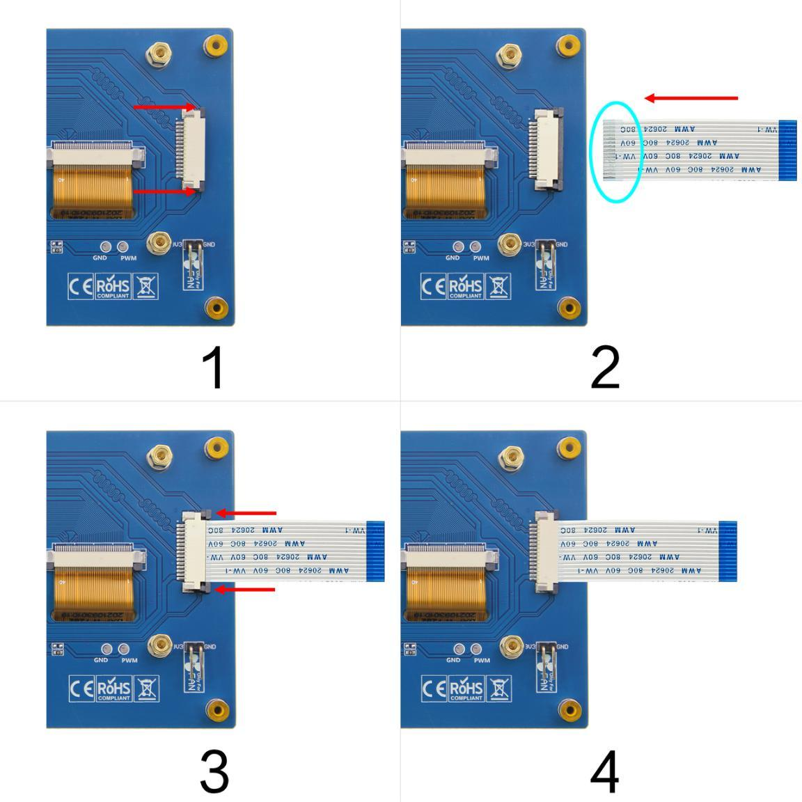
- Connect the DISPLAY module to the Raspberry Pi Display interface
through FPC flexible cable
- Connect the power cord to the Raspberry Pi
6) Power up the Raspberry Pi, and you can see that the program runs
normally. The module has display screen output, and the touch
function is normal.
Note: If the touch function or display is abnormal, find the
'dtoverlay=vc4-kms-v3d' in the /boot/config.txt file and change it
to 'dtoverlay=vc4-fkms-v3d', or comment it out
'#dtoverlay=vc4-kms-v3d'.
1) The copper column, screws and 15PIN FPC wiring are included in
the product accessories.
2) Figure 4 shows the installation of Raspberry Pi 4. The
installation method of Raspberry Pi 3 is basically the same as that
of Raspberry Pi 4. The only difference is that the power cord
connected is different. The Raspberry Pi 4 uses a Type-C cable and
the Raspberry Pi 3 uses a Micro USB cable.
Backlight Brightness Control Methods
Method 1: Adjust by pressing buttons
Click to increase by 10%, then return to 10% after reaching 100%;
Long press to turn off the backlight and press again to restore the
original brightness.
Method 2: Adjust by entering a command
- Find the 'dtoverlay=vc4-kms-v3d' in the /boot/config.txt file and
comment it out '#dtoverlay=vc4-kms-v3d'
2. Permission needs to be granted first (only need to run once
after each boot):
sudo chmod 777 /sys/class/backlight/rpi_backlight/brightness
3. Next step:
echo X > /sys/class/backlight/rpi_backlight/brightness
'X' indicates any number from 0 to 255. 0 indicates the darkest
backlight, and 255 indicates the brightest backlight (In this way,
the brightness adjustment will be recorded in the system and will
still take effect after the machine is restarted. The PWM mode is
not recorded and changes with the signal in real time.)
Method 3: Through PWM regulation
1) Make the hardware connection first. Adjusting mode according to
the hardware specifications, backlit by PWM adjust brightness value
way, so to backlight control mode selection circuit of resistance
welding to the PWM control circuit, the next on the PWM & GND
access points respectively welding dubond thread, finally will PWM
access points connected to the output PWM signals of Raspberry Pi
GPIO (select GPIO18), connect GND access points to Raspberry Pi GND
pin.

2) Software adjustment. The first step (which you can ignore if you
have already done it) is to connect the SD with the official image
to your PC, then create a new SSH file in the root directory of the
SD card, pop the SD card out, and insert it into the Raspberry Pi.
The above steps are to prepare for an SSH connection. Next, open
the PC terminal software (such as PuTTY, Securecrt, etc.), select
the SSH protocol, enter the Raspberry Pi IP address and log in the
Raspberry Pi terminal (the IP address can be viewed through the
router's web page or viewed on the Raspberry Pi through the
module).
3) On the Raspberry Pi terminal, enter the following command to
adjust the PWM backlight brightness (select GPIO18 here, and other
idle GPIO can also be selected):
gpio -g pwm 18 1024 gpio -g mode 18 pwm gpio pwmc 1000 gpio -g pwm
18 X (Control the brightness, X value between 0 and 1024)
In addition, add the following content at the end of
/boot/config.txt file to make the display module boot, PWM will
reach the maximum (the brightness of the display screen)
gpio=18=op,pu
Note: Backlight control on Raspberry Pi 4 will fail, you need to update
the WiringPi GPIO library by typing the following command
(Raspberry Pi requires Internet connection)
cd /tmp wget
https://project-downloads.drogon.net/wiringpi-latest.deb sudo dpkg
-i -B wiringpi-latest.deb
Display Rotation Configuration
There are two kinds of display direction rotation: FKMS mode
direction rotation and traditional graphics mode direction
rotation.
Method 1: FKMS mode direction rotation
FKMS mode is used by default on Raspberry Pi 4B.When using this
mode, make sure that "dtoverlay =vc4-fkms-v3d" under pi4 in
/boot/config.txt file is not commented out. In this mode, the
display direction can only be rotated by menu options. Note that
when setting the display direction in the menu, it is recommended
to use the mouse for operation.
Method 2: Traditional graphics mode
By default, the Raspberry Pi 3, 2, and 1 series use traditional
graphics mode. Raspberry Pi 4B can also use traditional graphics
mode, just in /boot/config.txt file under the Pi 4:
dtoverlay=vc4-fkms-v3d
Comment out, as shown (Traditional graphics mode is generally not
recommended on Raspberry Pi 4B). In traditional graphics mode, this
can be done by adding it at the end of the /boot/config.txt file:
display_lcd_rotate=x(x=0,1,2,3,0x10000,0x20000)
To set the display orientation, reboot is required to take effect.
display_lcd_rotate=0, The default normal display direction (no
rotation);
display_lcd_rotate=1, Rotate 90° clockwise;
display_lcd_rotate=2, Rotate 180° clockwise;
display_lcd_rotate=3, Rotate 270° clockwise;
display_lcd_rotate=0x10000, Flip horizontal;
display_lcd_rotate=0x20000, Flip vertical;
Note: There is a more convenient way to rotate display and touch at the
same time by rotating 180° clockwise. Please find the
'dtoverlay=vc4-kms-v3d' in the /boot/config.txt file and comment it
out '#dtoverlay=vc4-ms-v3d', and add the following statement at the
end of the file
display_rotate=2 lcd_rotate=2
After saving and restart, display and touch can be used normally
(only rotate 180°,other directions are not applicable)
Touch Rotation Configuration
The display direction is set, and the touch direction should be set
accordingly. It needs to correspond with the display direction,
otherwise the touch operation is not accurate. Touch direction
setting need to be in the
/usr/share/X11/xorg.conf.d/40-libinput.conf file add '<Option"
CalibrationMatrix " "XXX" > content, including XXX for touch
direction set parameters, the following will show. Open the
40-libinput.conf file:
sudo nano /usr/share/X11/xorg.conf.d/40-libinput.conf
After the modification, press Ctrl +X, Y, and Enter to save and
exit.
Corresponding relation table of display direction and touch
direction:
| Display Rotation | FKMS mode | Traditional graphics mode Settings | Touch orientation setting |
|---|
| no rotation | normal | display_lcd_rotate=0 | Option "CalibrationMatrix" "1 0 0 0 1 0 0 0 1" |
| Rotate 90° clockwise | right | display_lcd_rotate=1 | Option "CalibrationMatrix" "0 1 0 -1 0 1 0 0 1" |
| Rotate 180° clockwise | inverted | display_lcd_rotate=2 | Option "CalibrationMatrix" "-1 0 1 0 -1 1 0 0 1" |
| Rotate 270° clockwise | left | display_lcd_rotate=3 | Option "CalibrationMatrix" "0 -1 1 1 0 0 0 0 1" |
| Flip horizontal | NO | display_lcd_rotate=0x10000 | Option "CalibrationMatrix" "-1 0 1 0 1 0 0 0 1" |
| Flip vertical | NO | display_lcd_rotate=0x20000 | Option "CalibrationMatrix" "1 0 0 0 -1 1 0 0 1" |
Virtual Keyboard Installation
Execute the following command:
sudo apt-get install matchbox-keyboard








 4.3 Inch 800x480 Capacitive Touch Screen Display With IPS TFT Technology

